How To Build Your Very Own Graphics Engine

Disclaimer: This post will not teach you how to build your own graphics engine. It may, however, delight and confuse you.
In my previous post (which you can find here) I introduced what radiosity is along with why and how we want to use it. In this post I’m going to get into a little bit more technical detail on the bits and pieces that go into computer graphics in general and are used to help in the final calculation of radiosity. To begin with, I’ll talk about how the z-buffer is used to sort out which polygons are visible in a scene. Just to remind you, polygons are the shapes (here I use triangles) that make up any and every object in a virtual scene.
Buffering… Please Wait
So you’ve got your virtual scene, perhaps a room filled with virtual doggos, and you’ve figured out how to put a little camera in it to view the scene (with a fancy perspective projection?) but how do you figure out which parts of the scene are visible to you? In the real world it’s easy, light from objects behind other objects simply doesn’t reach your eye, but when rendering a virtual scene the computer isn’t sending out billions of rays of light and checking what hits its virtual eye, that would be far too expensive. Instead we have to be clever about it and one way to do this is by using the z-buffer.
The basic idea is simple, for every polygon in your view, for every pixel inside that polygon, compare the depth of that pixel (typically the z-coordinate, hence z-buffer) with the value currently in the z-buffer to decide which pixel should be displayed. For two intersecting polygons the final z-buffer and rendered image look like this.


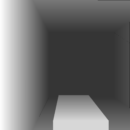
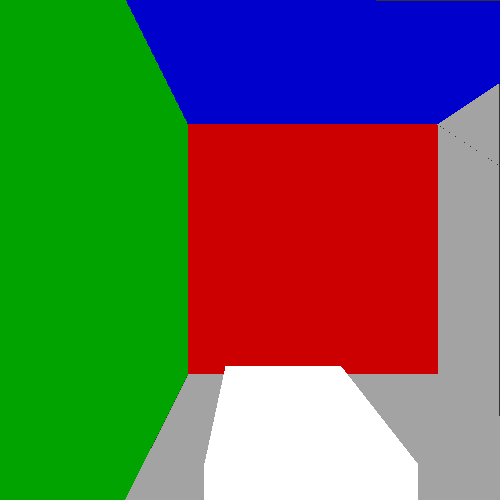
For a sample scene, a room with coloured walls and a white box inside, the z-buffer and final image looks like this.
Bro, Do You Even Clip?
During the projection step, but before we use the z-buffer, we choose a near plane, basically a kind of split in the scene separating polygons that are far from us from polygons that are too close to or behind the virtual camera. Any polygons in front of this plane should be rendered and any behind it should be discarded. However, there is the tricky situation of there being polygons that happen to have points on either side of the near plane. These polygons must be clipped, that is they are cut so that the bit that’s in front of the near plane remains and the bit behind it is discarded.
Below you can see the situations where no clipping is needed, where one point of the triangle is cut leaving two triangles, and lastly where two points are cut leaving just one smaller triangle.


Can You Make It Look Less… Tron?
So with the help of the techniques above I’ve actually managed to get a kind of first version completed of the rendering process. Check out the strange looking results below.
There’s a few things to notice that are wrong about the previous image. For one, it’s far too dark, radiosity must be being lost somewhere. Also, two neighbouring triangles should have similar shading values and it’s clearly seen in this image that the triangles seem to be forming a kind of stripy pattern. There’s also artifacts appearing between certain triangles because of the drawing method. The last problem I’m not too worried about but the first two are indicative of some kind of bug in the code. Maybe it’ll get fixed in time, maybe it won’t.
So it goes.

Leave a Reply