CAD is BAD !!

Caves , Castles and CAD data extraction – these are the three key subjects of focus in this blog. Now, having spent more than a month in Ljubljana, I have been able to make some progress not only in my SoHPC project but also in exploring this beautiful place. So, let’s have a deeper look into the things.

at the Predjama Castle
Over the past month, I got the chance to visit some of the magnificent sights in Slovenia including the Postojna Cave, the Predjama Castle and the Rakov Škocjan Valley. The feature picture is that of the Diamond which is the Symbol of the Postojna cave. It is around 5 meter high stalgamite formation and is snow white – as if truly shining like diamonds.
What is CAD ?
CAD stands for Computer Aided Design, which is a technical discipline dealing with the application of computers or “Super Computers” to the design of products used in everyday life. The CAD model contains the geometric details of the product and is created using a CAD modelling software such as SOLIDWORKS. As mentioned in my previous post , the CAD model serves as the starting point for various computer based design validation techniques (numerical simulation) including Finite Element Analysis and Computational Fluid Dynamics. The terms “CAD data” or simply “CAD” are many a times used to refer to the CAD model, a convention followed in this post from now on.
Why is CAD so bad after all ?
The CAD data as created by the designer, almost invariably contains many small details such as fillets, holes and small parts such as bolts and nuts which are not of much importance for the numerical simulation. An attempt to use this data directly for numerical simulation would result in much complex and sometimes even incorrect numerical models. Thus arises the need for CAD data extraction (also referred to as defeaturing or geometry cleanup) wherein, we extract the useful data from the CAD model. Usually, this is somehow handled manually within the pre-processor but is cumbersome and time consuming. As already mentioned in my previous post, this project aims at development of a utility for carrying out the defeaturing in a programmatic way and to automate the process.
How Do we correct it ?
Before we go into the technical details of how this utility works, it is essential to know the hierarchy of the topological entities used for modelling in OpenCASCADE.
Solid -> Shell -> Face -> Wire -> Edge -> Vertex
The flow chart below describes the steps followed in this utility for geometry cleanup
- Import the CAD data as a .STEP file and sort all the solids present in the model according to their volumes.
- Remove all the solids with volumes below a threshold, as these are likely to form nuts, bolts ans other small parts not required for simulation.
- Removal of fillets : This step can be subdivided into sub-tasks as done below.
- Loop over each solid, recognize if it contains fillets and determine the type of fillet
- Apply suitable algorithm for removing the fillet, depending on its type ( explained later in detail)
For the purpose of debugging(removing “bugs” /errors present, so that the code does what it is expected to do), we use simple geometry as input. The input and the modified CAD model for such an example is presented below.
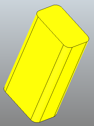
CAD Model of a Box with 4 isolated edge fillets
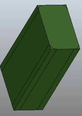
The modified model with the fillets removed
The next step in the process chain is the preparation of the CFD input files using the modified CAD data. A detailed description of this step along the different types of fillets handled in this utility will follow in the next post. So, stay tuned till then 🙂

Great Paras this was the real expectations from ur departure from India.