Computational fluid dynamics for clean society
My Project
My project is on Wind loading on solar trackers in Slovenia and is very interesting from a technological perspective as well as an environmental view and I use computational fluid dynamics as tool for the analysis. My project mentor Mr. Borris Jerman, he gave me brief introduction about the project and told me what needs to be achieved in this project. Actually this project involves many possibilities for analysis.These are:
1) Wind will not blow always in a same direction, different wind direction should be considered.
2) Solar trackers (solar panel) moves along with the sun, so different wind direction with different solar panel angles should be tested.
3) Terrain will not be same as always for example solar trackers can be placed on roof of the building and inclined places.
4) Run the simulation for more than one solar trackers to see how the wind load looks if the solar trackers arranged close to each other and continuously like in real case. In that case the boundary condition will be different for the second solar tracker.

Figure 1: pressure contour
What is CFD ?
Fluid mechanics problem (Partial differential equation) can be solved by using numerical methods (e.g., numerical solution of time-dependent partial differential equations) with help of computers. Since numerical methods are approximation method we can not expect accurate solution as the analytical solution. So in order to get good approximation the problem domain has to be discretized (e.g., finite volume, finite element, etc..) into small domain. Discretization will lead to multiple equations thus gives as a big matrix which should be solved through the iteration method to get a good a approximation. Super computer should be used to get faster solution.
Why CFD ?
Simulations are less expensive than the experiments because experiments consumes more energy and time. If the simulation data matches with the experimental data then we can do the simulation for similar cases. My work is to study how the wind load acts on the solar trackers using CFD because wind load causes more damage to the solar trackers.
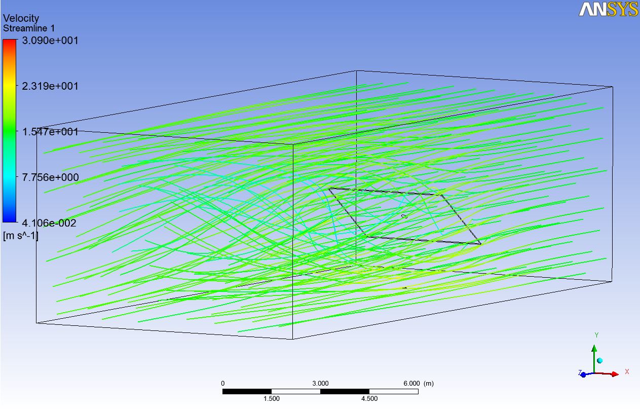
Figure 2: velocity streamlines
Better understanding of the wind loading on the solar tracker will encourage investors and policy makers for more installation of the solar trackers in the future and of course solar energy reduces the green house gas emissions.
My Project so far
Here is my test run of Wind loading on solar trackers using super computer from the HPCFS . Wind velocity is 15 m/s and solar panel dimensions are 4 m width, 3 m hight, lower edge is 0.7 meter above from the ground and the panel is tilted to 35 degree. Figure 1. shows the pressure on the solar tracker , as we can see here the pressure load is more on the bottom of the panel since that part is opposing the wind flow much. On the other side of the panel(backside) less pressure is experienced due to not much air flow. Figure 2. shows velocity streamlines on the solar tracker, here we can see little swirling and vortex are in the backside of the panel because of the wind flow behaviour. And also velocity is little higher around the solar panel after the air contact on the solar panel. Shear Stress Transportation(SST) solver was used to run the simulation and wall roughness was set as 0.5 mm.
What is next?
Fine tuning is need. Wind tunnel test data will be compared with the CFD simulation data. Different direction of wind and solar trackers with be simulated. Transient analysis shall be done to see real time visualization. Fluid-Solid interaction will be carried out to study how the deformation occurs in the solar panel due to wind load. Multiple solar panels together will be tested for different cases.

Nice work Mathi! Sounds like a really nice project with solar panels and all.
Thank you patrik !
HI anna Chetan here.,
Good to see you working on CFD for your thesis.
Project looks pretty good. But coming to some techinical questions, take care of your boundary conditions.
how think is the solar panel?
solar panel can not be kept open on any terrian i guess, it should be fixed to some surafec on the bottom side as far as i know.
Try to consider more realistic boudary conditions.
and what methods are you using to solve the equations like SST or K-omega or K-epsilon etcc..,
let me know if you need some help.
I wish you good luck .
Bye
Hi chetan ! thanks 🙂 I used the SST but this is my test simulation. I need to compare with wind tunnel data to see how it looks.If you take a look at the pressure contour plot you can see the tower or beam which holds the solar panel.Yes I need to work more on meshing and boundary condition. Sure I will let you know if i need any help 🙂